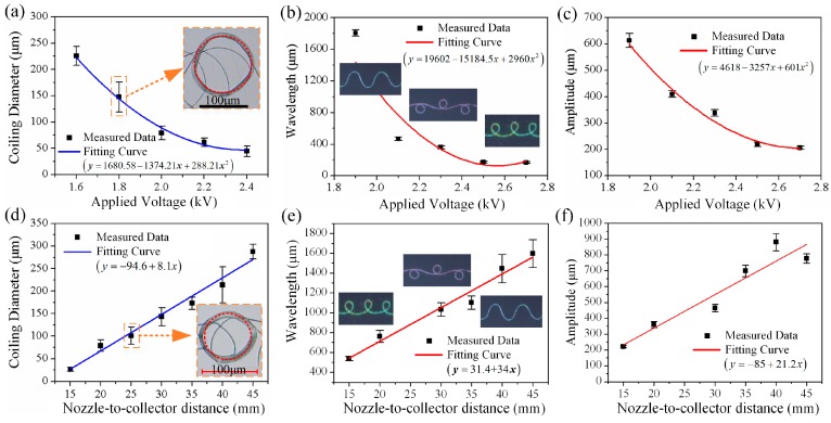
Figure 4.
(a) The coiling diameter versus applied voltage when Dcollector = 25 mm and Vcollector = 0 mm/s. (b,c) The wavelength and amplitude of different patterns versus applied voltage when Dcollector = 25 mm and Vcollector = 200 mm/s. (d) The coiling diameter versus nozzle-to-collector distance when Uapplied = 2.1 kV and Vcollector = 0 mm/s. (e,f) The wavelength and amplitude of different patterns versus nozzle-to-collector distance when Uapplied = 2.1 kV and Vcollector = 200 mm/s. The formulas in parentheses are the fitting equations of each fitted curve.

