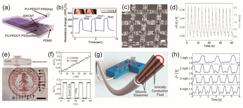
Figure 3.
Wearable strain sensors. (a) Schematic illustration of the cross-section of the strain sensor consisting of the three-layer stacked nano hybrid structure of polyurethane-poly(3,4-ethylenedioxythiophene) polystyrenesulfonate (PU-PEDOT:PSS)/single-wall carbon nanotube (SWCNT)/PU-PEDOT:PSS on a polydimethylsiloxane (PDMS) substrate. (b) Time-dependent ΔR/R0 responses of the sensor attached to the forehead when the subject was crying. Reprinted with permission from Ref. [34]. Copyright 2015, American Chemical Society. (c) Optical micrograph of a graphene woven fabrics (GWFs)-PDMS-tape composite film (scale bar 0.1 mm). (d) Relative change of resistance between 0% and 0.2% strain. Reprinted with permission from Ref. [86]. Copyright 2014, John Wiley and Sons. (e) Schematic illustration of stretchable capacitor with transparent electrode (top) and photograph of the same device reversibly adhered to a backlit liquid-crystal display (bottom) (scale bar 1 cm). (f) Change in capacitance ΔC/C0 versus strain ε (top) and ΔC/C0 versus time t over four cycles of stretching (bottom). Reprinted with permission from Ref. [69]. Copyright 2011, Nature Publishing Group. (g) Schematic image of multicore-shell printing process for fiber-type capacitive strain sensor. (h) Normalized decay time output of the sensor for different walking speeds up to 4 mph. Reprinted with permission from Ref. [92]. Copyright 2015, John Wiley and Sons.

