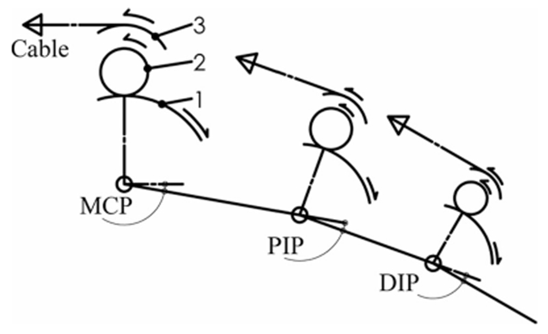
Fig. 1.

Three-link, planar model of CAFE. Transmission components are shown as arcs including: (1) the joint concentric gear, (2) small mating gear, and (3) joint pulley. Respective motions are indicated via arrows as an example of creating flexion at each joint.
