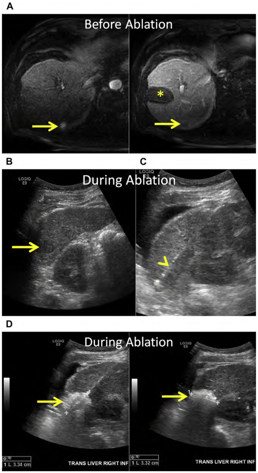
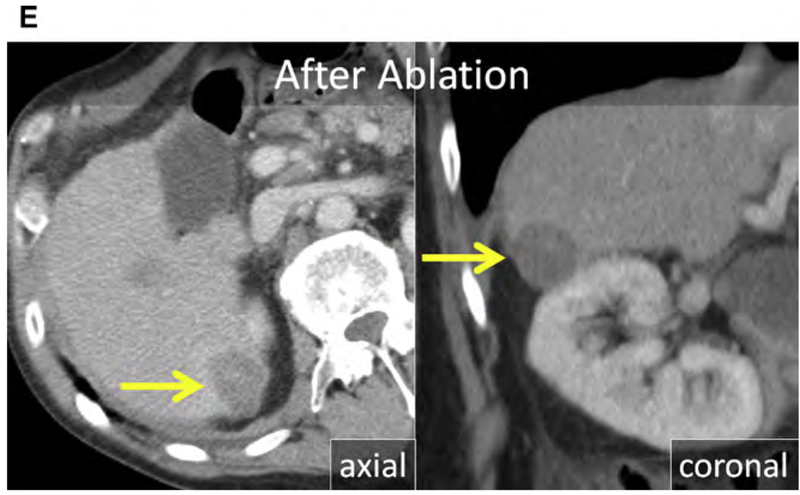
Fig. 6.
(A) HCC in the inferior right liver (arrows). Note the prior ablation in the right midliver (asterisk) without LTP. (B–D) US before and during ablation with the patient in left decubitus position. (B) At US, the HCC is hypoechoic (arrow). (C) US image after hydrodissection and placement of the MW antenna (arrowhead). (D) The gas cloud formed during MW ablation can be used to determine adequate coverage of the tumor and margin (arrows). (E) Axial and coronal enhanced CT immediately following MW ablation. The 3.3-cm ablation encompasses the index lesion, includes a margin greater than 5 mm, and corresponds with the size of the gas cloud at US (arrows).


