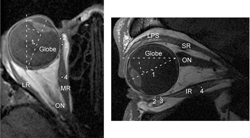
Figure 2:

Axial and quasi-sagittal magnetic resonance imaging (MRI) of the orbit. Left) Axial images were rotated to bring the midline of the nose to scanner vertical. The angle of globe rotation into adduction or abduction was then measured by drawing a line from the center of the cornea through the center of the lens towards the posterior globe and measuring the angle displacement of that line from scanner vertical (dashed lines). The center of the globe, marked with a white pixel (1), was determined by manually outlining the globe, then using the “Area Centroid” function of ImageJ64 to find its center. The posterior aspect of the cornea was used to delineate the globe’s anterior extent for this measure. White pixels were also used to mark the extraocular (EOM) insertion (2), immediate posterior tendon path (3), and middle of the posterior EOM belly (4). Right) For quasi-sagittal MRI, the angle of globe rotation into infraduction or supraduction was measured by a drawing a line from the center of the cornea through the center of the lens towards the posterior globe and measuring the angle displacement of that line from scanner horizontal (dashed lines). The center of the globe (1), EOM insertion (2), immediate posterior tendon path (3), and center of the posterior EOM belly (4) were defined the same as for the axial MRI. LR = Lateral Rectus; MR = Medial Rectus; ON = Optic Nerve; LPS = Levator Palpebrae Superioris; SR = Superior Rectus; IR = Inferior Rectus.
