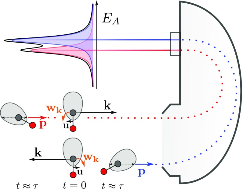
Fig. 1.
Classical picture of the dynamical rotational Doppler effect. In Bottom, a photoelectron with momentum is at ejected from the carbon atom (long black arrow) in the direction away from the detector. Induced by the recoil momentum, the molecule translates with a velocity and rotates with an angular velocity toward the detector. Therefore, an Auger electron with momentum emitted at toward the detector is blue shifted as indicated in the schematic spectrum displayed in Top. In Middle, the photoelectron is emitted in the opposite direction so that velocity and angular velocity are inverted, resulting in a red-shifted Auger electron in the detector. The shaded gray areas around the carbon atoms represent an Auger emission with anisotropic angular distribution in the molecular frame. In Bottom, the preferred direction of the Auger emission is rotated from the top toward the detector so that the blue-shifted Auger peak gains intensity as indicated by the long thin black arrow in the gray area. The opposite rotation in Middle lowers the intensity for the red-shifted Auger peak (short thin black arrow).

