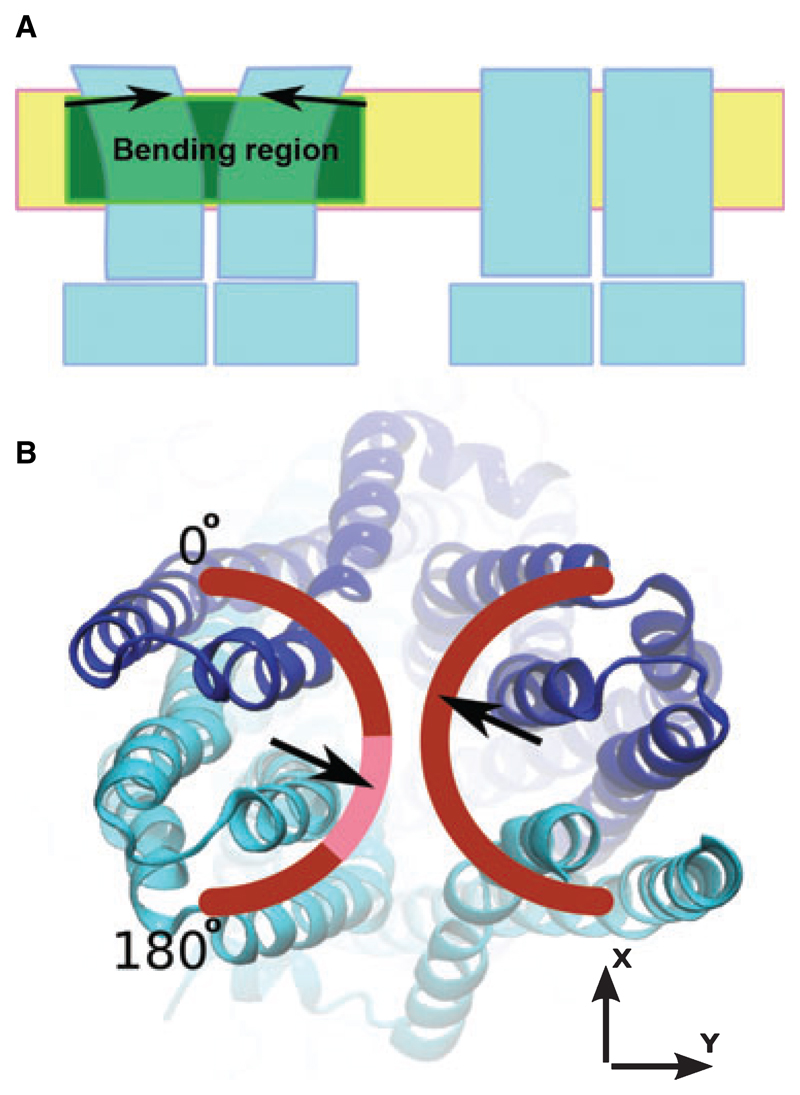
Fig. 1.
(A) Principle of the bending procedure applied to the TMDs of the initial P-gp homology model. The coordinates of the intra-cellular part remained unchanged. The bending region, placed in a section of the protein predicted to be in contact with the hydrophobic core of the membrane, is shown in green. As indicated by the arrows, the extracellular portion of the transporter was rigidly rotated by 10° (referred to as the ‘bending angle’ in the text). (B) The range of tested bending directions, which were sampled in 5° increments in the range 0–180°. The highlighted part of the arch indicates the bending directions that resulted in models that complied best with experimental cross-linking data. The two halves were bent symmetrically.

