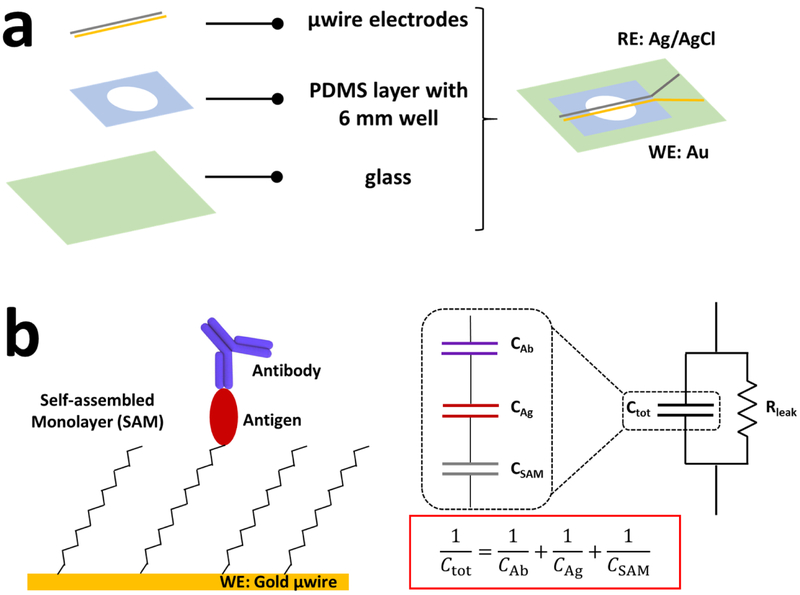
Figure 1.
Schematic of capacitive immunosensor design and working principles. (a) Device layers and resulting immunosensor shown from the top. RE: reference electrode, WE: working electrode; (b) Working electrode (Au microwire) surface chemistry and functionalized layers, with the corresponding equivalent circuit and total capacitance equation. DL capacitance, CDL, is placed in parallel with a leakage resistance, Rleak. CDL represents the total capacitance, Ctot, of the individual capacitance contribution from each surface layer.

