Fig. 3.

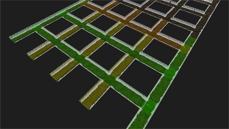
A visual depiction of the areas of influence of an example mesh node communication system. According to the implemented logic, the areas in green have full coverage that degrades through yellow, orange, and red to no coverage in dark areas

A visual depiction of the areas of influence of an example mesh node communication system. According to the implemented logic, the areas in green have full coverage that degrades through yellow, orange, and red to no coverage in dark areas