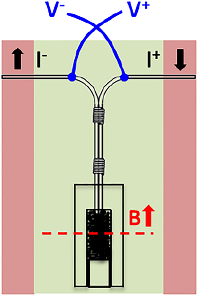
Figure 8.
A schematic illustration of the test setup for measuring joint transport properties at 4.2 K in magnetic fields. The field direction is parallel to the wire axis at the joint section, as indicated by the red arrow. The background field center lies at the physical center of the exposed Bi-2212 ends, as indicated by the red dashed line.

