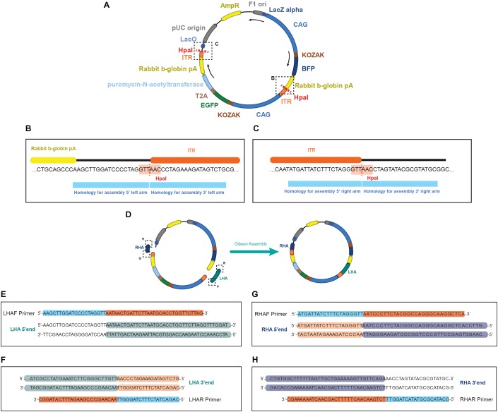
FIGURE 3.
Schematics of the EGFP donor plasmid and the homology in the primers for performing the assembly. (A) Representation of the pDONOR-tagBFP-PSM-EGFP with the restriction sites of HpaI. (B) Close up of the HpaI region where the left homology arm will be assembled. (C) Close up of the HpaI region where the right homology arm will be assembled. (D) Representation of the donor after assembly. On each primer from (E–H) it is represented in light blue the homology to the donor and in orange the homology to the genomic region of the example. Every double stranded DNA section in E–H represents the sequence of the homology arms to be assembled, showing in green (E,F) the genomic sequence incorporated in the left arm, and in dark blue (G,H) the genomic sequence incorporated in the right arm. In light orange (F,G) the homology in the arms to the ITR sequence of the donor, and unlabeled (E,H) the backbone of the donor plasmid.

