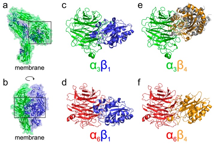
Figure 6.
Docking of α/β integrin N-terminal domains. (a,b) An example of resting state structure of extracellular domains of the α3β1 integrin as obtained from I-TASSER homology modelling. As expected from the crystal structures available for threading by I-TASSER the overall architecture of the resulting model is similar to αXβ2 (PDB ID 4neh; [12]) or αIIbβ3 (PDB ID 3fcs; [13]) heterodimer structures. The interacting region of N-terminal domains is highlighted by the black rectangle. Panel (a) shows the α3 subunit on top of the β1 domains, while panel (b) represents the same structure rotated by 90 degrees orienting both the N-terminal domains to the front of the image. (c–f) The predicted arrangement of heterodimers formed by N-terminal domains of integrins α3β1 (c), α6β1 (d), α3β4 (e), and α6β4 (f) from the flexible side chain docking of the domains by ClusPro. In the case of α3β4 (f) two binding modes are shown. The predicted most stable dimer with the β4 domain (orange) interacting through the NV residues homologous with the typical Arg/Lys finger of β domains is compared to an alternative, less stable binding mode, employing the RPEK sequence (grey). Both binding modes are similar and suggest that the α3β4 complex adopts different domain orientation compared to the remaining α3β1, α6β1, and α6β4 cases. The α3 domains are shown in green, β1 in blue, α6 in red, and β4 in orange.

