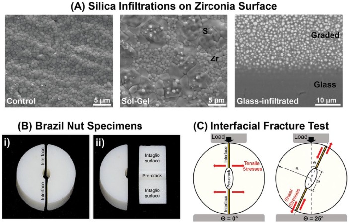
Figure 1.
Description of the study design: (A) Scanning electron microscopy images showing the microstructure of the zirconia used in this study, from left to right; as machined (InCeram YZ), the sol-gel–treated zirconia (surface view) with silica islands intermingled within zirconia grains and the glass-infiltrated zirconia, which was polished in a shallow angle to expose the underlying zirconia/glass graded layer. (B) Digital photograph of a Brazil nut specimen: i) side view of the 2 halves and ii) detail of the intaglio surface and precrack on one of the halves. (C) Schematic of the load-to-fracture test setup, where 2a is the crack length, R is the radius of the Brazil nut specimen, and Θ is the angle between the loading direction and crack orientation. At Θ = 0° and Θ = 25°, illustration of the direction of stresses applied to the bonded interface is shown.

