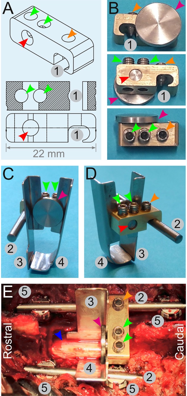
Figure 7.

Engineering of a spinal cord support system. (A,B) Drawings (A) and pictures (B) for the engineering of a link element. It is composed of an indentation (1) to affix it onto a rod (2) by a screw (orange arrowheads). Two other screws (green arrowhead) tighten or release a small cylinder (red arrowhead) terminated by a disc (magenta arrowhead). Tightening of these screws (green arrowheads) pulls on the cylinder and presses the disc against the edge of the link element. This is used to affix two plates (C,D)—one straight (3), and the other is bended (4). (E) Assembly of the spinal cord support system in vivo. Four pedicle screws (5) are inserted and two rods (2) are fitted and secured on the screws to fuse three adjacent spinal segments. The link element is attached to the longest spinal rod. The plates (3 and 4) encompassing the spinal cord (blue arrowhead) are firmly pressed against the link element by the disc (magenta arrowhead). All the numbering and colored arrowheads are consistent throughout this figure.
