
Fig. 4. In-plane magnetic anisotropy enforced by the orthorhombic substrate.
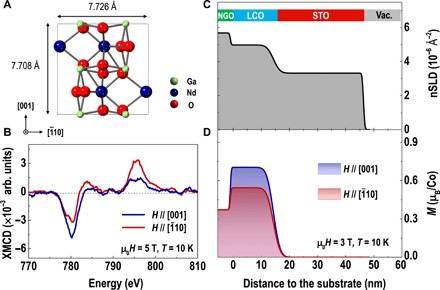
(A) The top view lattice structure of orthorhombic (110)-oriented NGO. The in-plane lattice parameter along the [10] orientation is larger than that along the [001] orientation, leading to in-plane anisotropic shear strain in LCO films. (B) XMCD spectra for Co L-edge at 10 K with a magnetic field of 5 T applied along the [10] and [001] orientations. The XMCD signals were calculated from the difference between the μ+ and μ− divided by their sum, as described by (μ+ − μ−)/(μ+ + μ−), where μ+ and μ− denote XAS obtained from the right- and left-hand circular polarized photons, respectively. (C) Nuclear scattering length density (nSLD) and (D) magnetic moment (derived from the magnetic scattering length density, mSLD) depth profiles of an LCO film. The inset of (C) shows the schematic of the sample geometry. The LCO film was grown on a NGO substrate and then capped with a STO thin layer to prevent loss of oxygen at the LCO surface. PNR measurements were performed at 10 K after field cooling in 3 T. The magnetic field was applied along the [10] and [001] orientations, respectively.