Fig. 2.
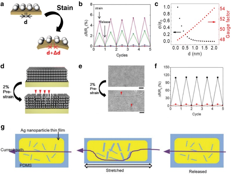
a Schematic of NC thin films after applied strain. b Cycle tests with application of 0.2% strain on MPA—(purple), EDT—(green), Cl—(red), and Br—(blue) treated Ag NC thin films. c Conductivity and gauge factor of NC thin films as a function of initial interparticle distance. d Schematics of crack formation strategy. e SEM images of Ag NC thin films after crack formation. f Cycle tests with application of 0.2% strain on MPA-treated Ag NC thin films before (red) and after (black) crack formation and g schematic of current path change of Ag NC thin films with cracks after the strain application
(Figure reproduced from a, b, and d–f [50], Copyright 2017, Royal Society of Chemistry; c [59], Copyright 2017, Wiley-VCH; g [60] Copyright 2014, Royal Society of Chemistry)

