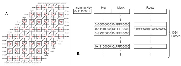
Figure 2.
(A) The SpiNNaker Board wiring, showing the links between the chips on a single board, and the numbering of the links and chips. (B) The SpiNNaker Routing tables. An incoming key is matched against the entries in the table using the mask to determine which bits can be ignored and a route is determined, made up of 6 link bits and 18 processor bits, indicating where the packet should be sent. An entry might match with multiple keys once masked, in which case the match that appears earliest in the table is used.

