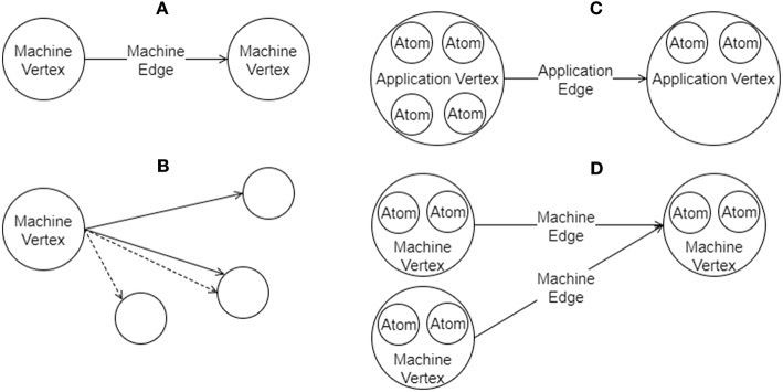
Figure 4.
Graphs in SpiNNTools. (A) A Machine Graph made up of two Machine Vertices connected by a Machine Edge, indicating a flow of data from the first to the second. (B) A Machine Vertex sends two different types of data to two subsets of destination vertices using two different Outgoing Edge Partitions, identified by solid and dashed lines, respectively. (C) An Applications Graph made up of two Application Vertices, each of which contain two and four atoms, respectively, connected by an Application Edge, indicating a flow of data from the first to the second. (D) A Machine Graph created from the Application Graph in (C) by splitting the first Application Vertex into two Machine Vertices, each of which contain two atoms. The second Application Vertex has not been split. Machine Edges have been added so that the flow of data between the vertices in still correct.

