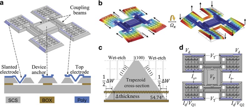
Figure 2.
Anisotropically wet-etched gyroscope geometry and mode shapes. (a) Device geometry: colored regions indicate the transduction surfaces. Cross-sectional view shows the shape of the gyroscope body and polysilicon electrode at different locations. (b) Mode shapes of the in-plane mode and the out-of-plane mode. (c) Cross-section of a coupling beam showing the linear dependency of the beam bottom width on the device thickness. In the presence of a device thickness variation, the distance from the top surface to the actual BOX layer (dotted outline) differs from the distance to the ideal BOX layer (solid outline), causing the bottom width of the beam to vary correspondingly. (d) Electrode configuration of the gyroscope. Differential sense output is enabled by using the out-of-plane (OOP) mode as the sense mode to reject common-mode errors.

