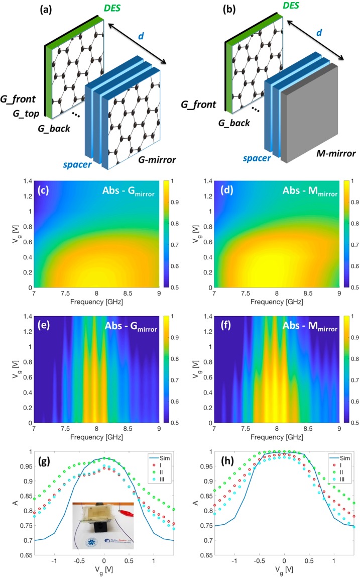
Figure 5.
Sketch of the Salisbury screen realized by sandwiching the glass spacer between the electrochemical capacitor and the (a) graphene-based and (b) metallic mirrors, respectively. In both configurations the spacer thickness d is equal to 3.8 mm in analogy to what has been done in ref.13. (c,d) Theoretical and (e,f) experimental absorption maps for (c–e) G-mirror and (d–f) M-mirror. (g,h) Absorption versus gate voltage Vg for three maxima (I - first at 7.84 GHz, II - second at 7.97 GHz and III -third at 8.11 GHz). The blue line corresponds to the numerical absorption at 7.97 GHz. Inset (g) picture of the transparent absorber based on the Salisbury screen configuration.

