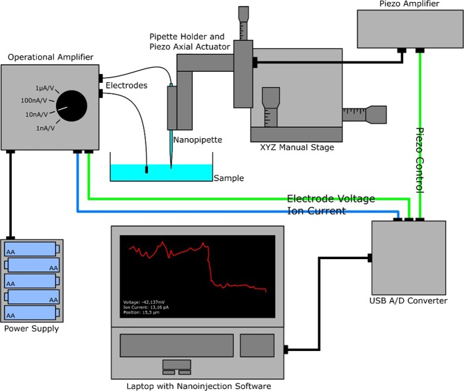
Figure 1.
Schematics of the mobile nanoinjection setup. The entire system is monitored and synchronized with a small USB data acquisition interface controlled by our nanoinjection software. Two analog output channels (green wires) are used to provide voltage for the electrodes (channel AO 0) and to control the pipette movement (channel AO 1) via a piezo actuator. The ion current is amplified by a custom operational amplifier and converted according to a selectable range to ±10 V to then be sent to the analog input channel (AI 0) of the USB A/D converter (blue wire). As a power supply for the amplifier, either a conventional power supply or a 15 V battery pack can be used to gain additional flexibility.

