
Figure 1.
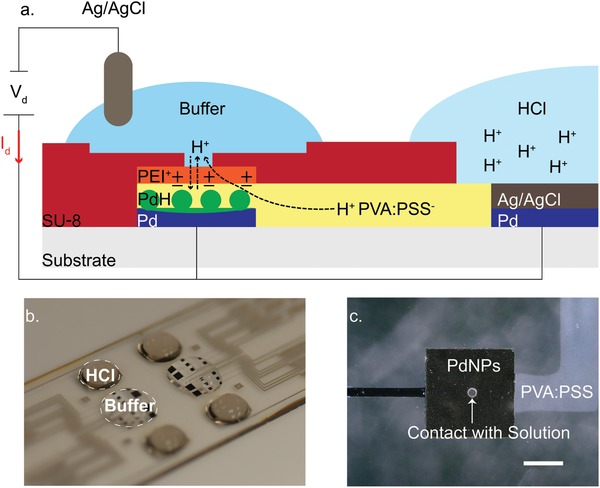
a) Schematic of pH modulator, and operating principle of bioelectronic pH modulator. Two electrolyte chambers are connected with an H+ conducting membrane. A high [H+] solution (right) is at the interface with a modified Pd/Ag/AgCl. A buffer solution (left) is at the interface with PdNPs and an Ag/AgCl pellet immersed in solution. Application of V d = 1 V between PdNPs‐Pd/Ag/AgCl (working electrode) and Ag/AgCl pellet (reference electrode) decreases the buffer potential with respect to reservoir, and H+ are transferred from the reservoir (right) into the buffer solution and thus decrease its pH. Application of V d = −1 V increases the potential of the buffer solution, and H+ are transferred and stored into the PdNPs, thus the pH of the buffer solution is increasing. b) Perspective photo of the device showing the reservoir loaded with acid (HCl) on top of the Pd/Ag/AgCl electrode and the active area with buffer on top of the PdNPs electrodes. c) Optical image showing a close up of a PdNPs contact, the proton bridge, and SU8 pore (40 µm) at the PdNPs/solution interface, scale bar 200 µm.