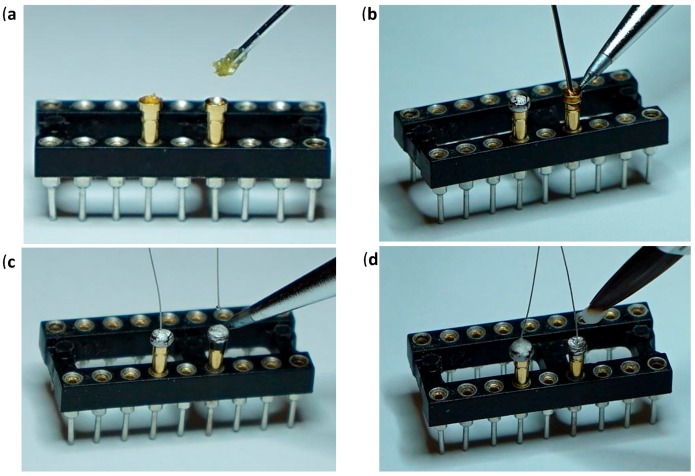
Figure 4.
Gold Pin Wire; (a) Insertion of the appropriate number of gold pins to the dip socket and application of liquid paste flux to the gold pin mounting holes. (b) Gold pin mounting holes filling with lead-free solder. (c) Solder re-melting and insertion of the 6.9 cm PI wires. (d) Acrylic covering of gold pin top end.

