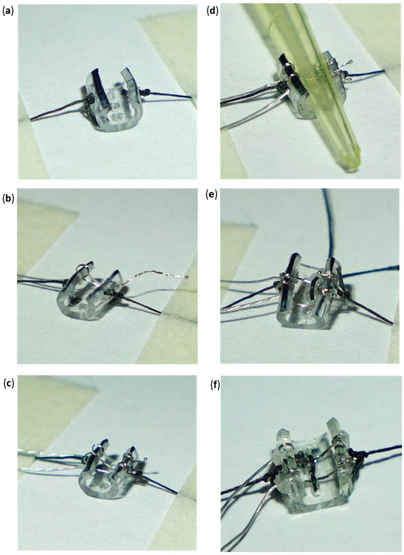
Figure 6.
(a) Cuff skeleton secured through lateral silk strands to expose the inside of the tube. (b) PI wire with gold pins looped once at the left superior hole and moved across the right superior hole. Only uninsulated PI wire exists inside of the tube. (c) Gold pin wires assembled into their respective locations. PI wires have been looped twice at the right superior and inferior holes. (d) Pressing of the two looped gold pin wires using a 10 µL pipette tip against the inside wall of the cuff skeleton. (e) Silk “D Loop” formed between the upper and middle posterior holes. (f) Completed standard cuff. Inside silk knotting follows a zigzag pattern. Minimal application of acrylic is desired.

