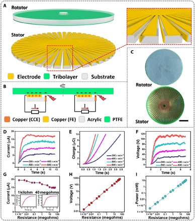
Fig. 3. Working mechanism and output performance of the rotary mode DC-TENG.

(A) Structural design of the rotary mode DC-TENG. Inset shows a zoomed-in illustration of its stator. (B) Working mechanism of the rotary mode DC-TENG. (C) Photographs of the fabricated rotary mode DC-TENG. Scale bar, 5 cm. (D) Short-circuit current, (E) transferred charges, and (F) open-circuit voltage of the rotary mode DC-TENG at different rotation rates (300, 400, 500, and 600 r min−1). (G) Output current of the rotary mode DC-TENG with various resistances. Inset shows the detailed output current at 1 kilohm and 40 megohms. (H) Output voltage and (I) power of the rotary mode DC-TENG with various resistances.
