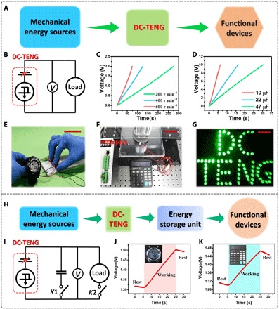
Fig. 4. Application of the DC-TENG to drive electronic devices.

(A) System diagram and (B) circuit diagram of a DC-TENG–based self-powered system to power electronics directly. (C) Measured voltage of a capacitor (470 μF) charged by a rotary mode DC-TENG at different rotation rates. (D) Charging curves of capacitors with various capacitance charged by a rotary mode DC-TENG at a rotating speed of 500 r min−1. (E) Photograph of a watch directly driven by a sliding mode DC-TENG. (F) Photograph of a scientific calculator directly driven by a rotary mode DC-TENG. (G) Photograph of 81 LEDs with stable luminance powered by a rotary mode DC-TENG. (H) System diagram and (I) circuit diagram of the self-powered system to power electronics with energy storage units. (J) Charging curves of the capacitor when the watch is driven by a rotary mode DC-TENG simultaneously. (K) Charging curves of the capacitor when the scientific calculator is driven by a rotary mode DC-TENG simultaneously. Scale bars, 5 cm. Photo credit for (E), (F), (G), (J), and (K): X. Yin, Chinese Academy of Sciences.
