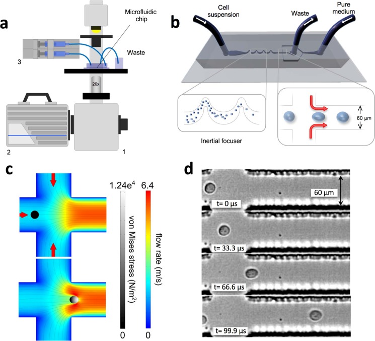
Figure 1.
Experimental set-up and mechanical phenotyping. (a) Schematic diagram of the hydrodynamic stretching platform. The microfluidic chip is on a standard inverted microscope (1). A high-speed camera (2) is used to record the cell deformation and a syringe pump (3) is used to independently control the flow rate that transports the cell suspension and the pure medium used to create the pinching flow. (b) Schematic diagram of the microfluidic chip. The inertial focuser focuses the cell suspension down to a single streak of evenly spaced cells towards the centre of the channel, which are then deformed by the pinching flow. The output of the chip is simply routed and collected into a container. After the mechanical stretching, cells are still viable (survival rate of 94.7 ± 2.2%, averaged over three independent experiments) and therefore the output suspension could potentially be subjected to further analyses. (c) Simulated fluid velocity profile at the mid-plane of the channel at the junction where the pinching streams join the main channel, in the case of an unperturbed cell and a cell at the position of maximum deformation, respectively. The von Mises stress profile in the cell is represented by brightness (grey scale). (d) A DU145 cell deforms as a result of the pinching flow. Before entering the pinching region, the cell is unperturbed and hence its shape is almost spherical. In the second frame the cell starts to experience the effect of the pinched flow and it is slightly deformed. The deformation reaches its maximum in the third frame and it relaxes to a residual deformation.

