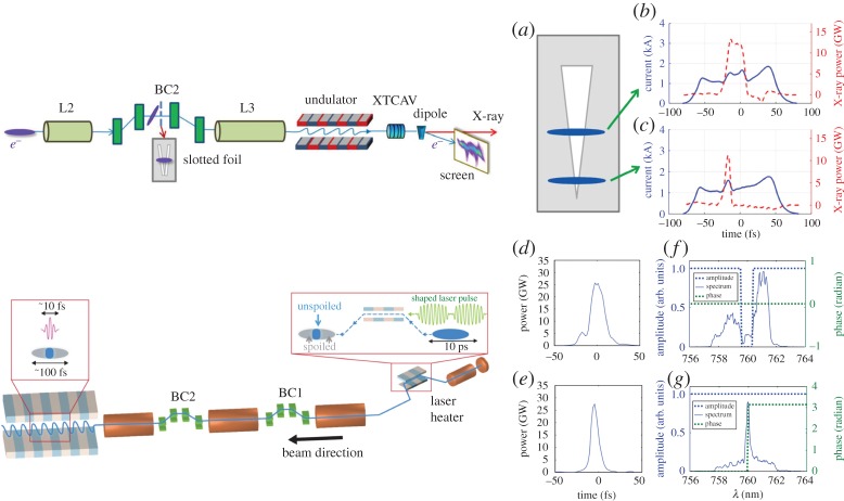
Figure 1.
Schematic view (top, left side) of the emittance spoiler (a) and X-ray temporal profile (b and c) measured with a transverse cavity for different spoiler settings (from [25]). Schematic view (bottom, left side) of the optical shaping scheme and X-ray temporal profile (d,e) measured with a transverse cavity for different laser heater shapes, amplitude and phase (f,g) measured after amplification (from [28]). (Online version in colour.)

