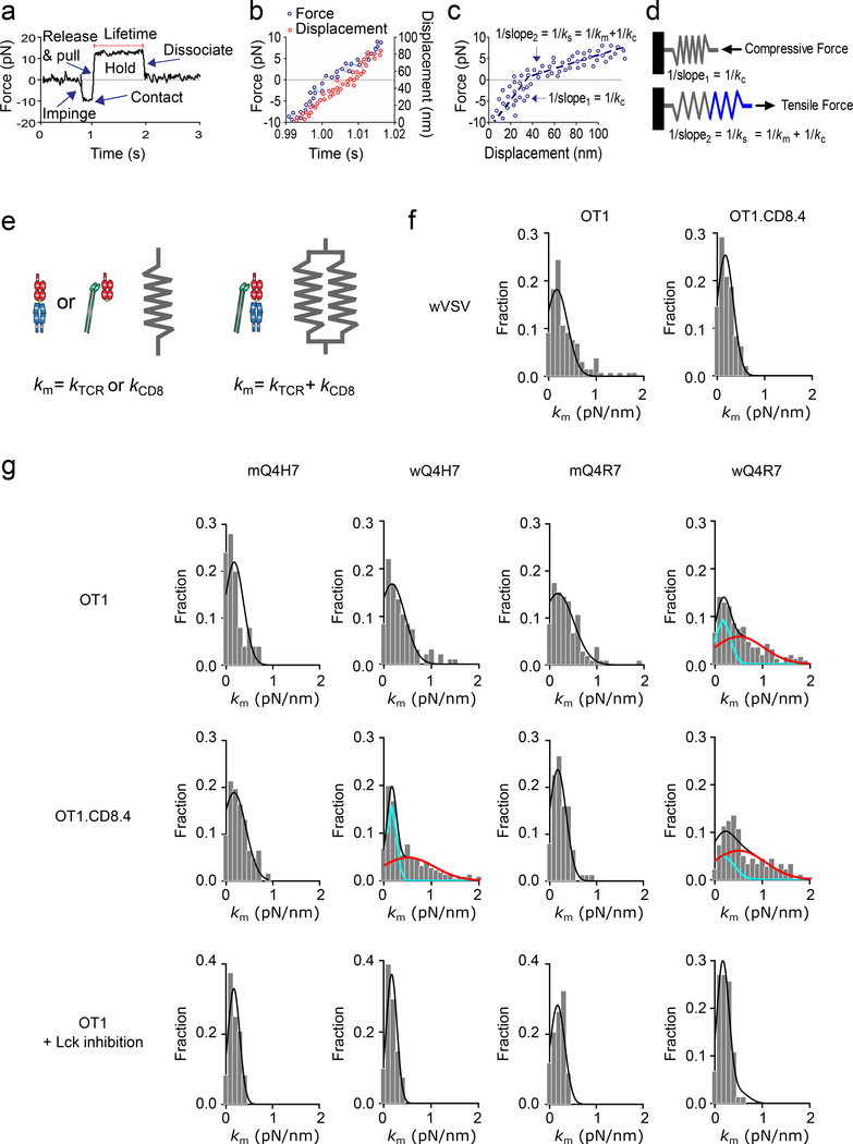
Figure 2 |. Molecular Stiffness Analysis Distinguishes Heterodimeric and Monomeric Bonds.
a, A representative force vs. time trace of a BFP force-clamp assay cycle. Indicated are thymocyte impingement to and contact with the BFP bead, retraction to release compression and to pull with an increasing tension, and holding on a clamp force for lifetime measurement until bond dissociation. b, Force (left ordinate, blue) and displacement (right ordinate, red) vs. time data corresponding to the increasing force portion in (a). c, Force vs. displacement data obtained by combining the two sets of data from (b) to eliminate time. Two line segments (blue dashed lines) were fit to data to evaluate the compliances 1/kc and 1/ks (= reciprocal slopes of the two lines). d, The molecular spring constant km is solved from 1/ks = 1/kc + 1/km because for two springs in series, the system compliance equals the sum of compliances of the two springs. e, Mechanical model for the TCR–pMHC and MHC–CD8 monomeric complexes (one spring) and for the TCR–pMHC–CD8 heterodimeric complex (two springs in parallel). f, Molecular stiffness histograms of bimolecular bonds of wVSV with CD8 on OT1 (left) or OT1.CD8.4 (right) thymocytes. g, The first and second rows show data from untreated OT1 and OT1.CD8.4 thymocytes, respectively. The third row shows data from Lck inhibitor-treated OT1 thymocytes. The left two columns show Q4H7 data whereas the right two columns show Q4R7 data. The peptides are labeled by “m” or “w” to indicate whether they were presented by the MT or WT MHC. Molecular stiffness histograms of monomeric bonds of TCR with mQ4H7 (1st column) or mQ4R7 (3rd column), or total bonds with wQ4H7 (2nd column) or wQ4R7 (4th column). Data (bar) were fitted by a single (black curve) or double (black curve = cyan curve + red curve) Gaussian. The fitting parameters and statistics for their comparisons are summarized in Supplementary Tables 4 and 5a.

