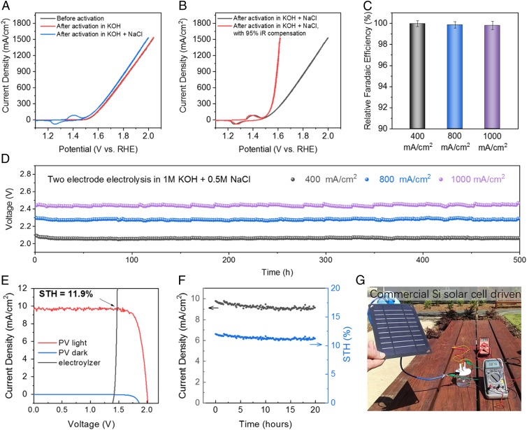
Fig. 3.
Seawater electrolysis running at current density up to 1 A/cm2. (A) CV scans of a 0.25-cm2 Ni3 anode before and after activation in 1 M KOH and 1 M KOH + 0.5 M NaCl (both at 400 mA/cm2); the CV curves were taken in simulated alkaline seawater (1 M KOH + 0.5 M NaCl), resistance 1.2 ± 0.05 ohm. (B) CV scans with and without iR compensation of the 0.25-cm2 Ni3 anode shown in A. (C) Two electrode R_FEs of oxygen generation in seawater electrolyzer (Ni3 paired with Ni-NiO-Cr2O3) running at 400 mA/cm2, 800 mA/cm2, and 1,000 mA/cm2 in 1 M KOH + 0.5 M NaCl electrolyte. (D) Durability tests of the seawater-splitting electrolyzer (0.5 cm2 Ni3 paired with Ni-NiO-Cr2O3) recorded in 1 M KOH + 0.5 M NaCl electrolyte at room temperature under constant currents of 400 mA/cm2 (R = 1.5 ± 0.05 ohms), 800 mA/cm2 (R = 1.6 ± 0.05 ohms), and 1,000 mA/cm2 (R = 1.6 ± 0.05 ohms), respectively. Data were recorded after activation of Ni3 anode under 400 mA/cm2 in both 1 M KOH and 1 M KOH + 0.5 M NaCl electrolytes for 12 h. (E) Current density–potential curve (J–V) of the seawater electrolyzer and two perovskite tandem cells under dark and simulated AM 1.5-G 100 mW⋅cm−2 illumination. The illuminated surface area of each perovskite cell was 0.12 cm2 (0.24 cm2 total), and the catalyst electrode areas (geometric) were 1 cm2 each. The Ni3 were first activated in 1 M KOH under 400 mA/cm2 for 12 h then in 1 M KOH + 0.5 M NaCl under 100 mA/cm2 for 12 h. After that the electrolyzer was held at 20 mA/cm2 for 5 h before pairing with the solar cell. (F) Twenty-hour stability test of perovskite solar cell-driven seawater electrolysis and corresponding solar-to-hydrogen (STH) efficiency. (G) A photo showing a commercial silicon solar cell-driven electrolysis (1-cm2 electrodes) of seawater running at 876 mA under a voltage of 2.75 V (R = 1.0 ± 0.05 ohms). No iR compensation was applied to any experiment.

