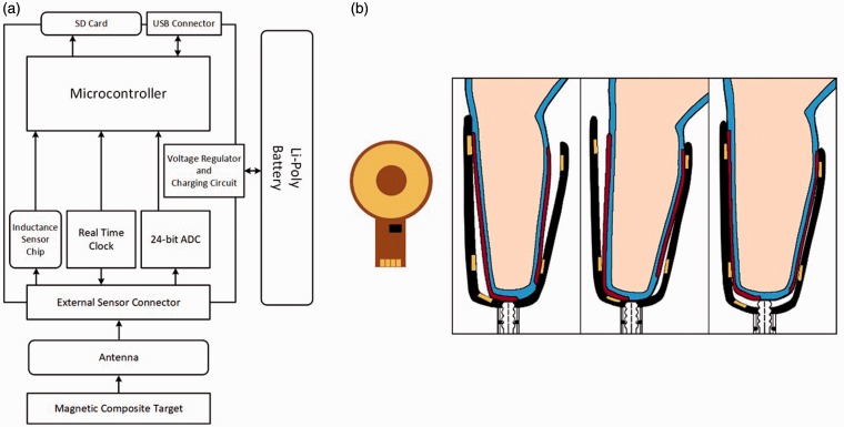
Figure 1.
Sensor system. (a) Block diagram showing arrangement of sensor components. (b) Antenna and instrumented socket. Left: A schematic of the antenna. The black rectangle is the tank capacitor. Right: The regions of the composite sheath embedded with magnetic particles are shown as red stripes. The gold areas on the socket represent the antennas embedded within the socket. The blue layer is the elastomeric prosthetic liner.

