
Fig. 11.
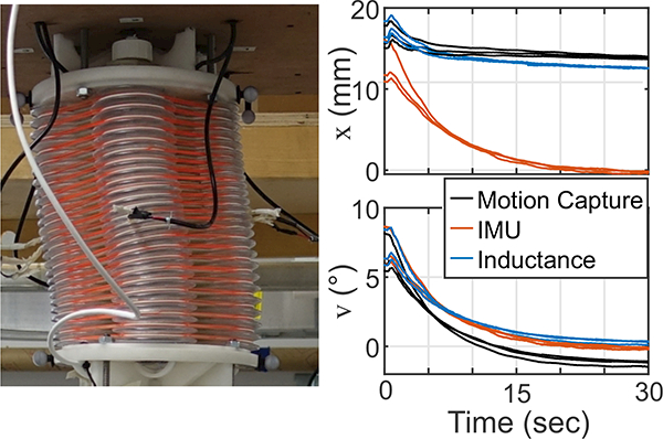
The photo shows the level joint with a forced, 14 mm displacement in the direction of bellows 1 (x). In this condition, the bending in one half of the joint is counteracted by bending in the other half. Also shown are the estimates of the lateral displacement x and the orientation v from the three lateral displacement tests. The lateral displacement predicted by the IMU (red) assumes the joint has a constant curvature across its entire length. As the angle of the joint approaches zero, the IMU displacement estimates (red) also approach zero. The inductance-predicted displacement (blue) remains close to the position recorded by the motion capture system (black). The inductance-predicted estimate of the orientation v also remains close to that measured by the IMU (most accurate).