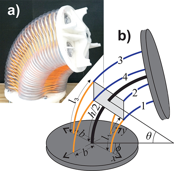
Fig. 4.

(a) Photo of a 2-DOF bellows-driven continuum joint. The orange fibers constrain the bellows around the central cable. (b) The kinematic model of the joint. Each half of the joint undergoes a bend angle 𝜃 with an orientation ϕ. The center of the joint is reinforced by a cable of length h (thick black line). The bellows are indexed from one to four. The center-lines of the half bellows (thin blue and orange lines) have lengths of l1, l2, l3 and l4. The centers of the bellows are spaced from the central cable by a distance b.
