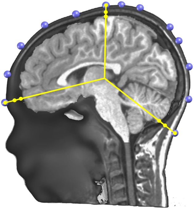
Figure 6.

Illustration of the determination of the skull thickness under each electrode. A sagittal cutting plane is shown with the electrodes (in blue) located on the scalp surface, the radius lines (in yellow) extending from the center to each electrode, and on each line three dots showing where the skull and scalp limits are determined.
