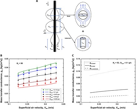
Fig. 4. Mass transfer conductance.

(A) Schematic illustrating the decomposition of the water film into two components: (i) each water bead as a sphere in a uniform air stream of velocity Vair + Vbead (to account for the bead velocity) and (ii) a stationary water cylinder with the same diameter as the liquid substrate coating the string in a uniform air stream of velocity Vair. (B) The experimental and predicted mass transfer conductances as a function of the superficial air velocity for the dehumidifier with 96 strings. Various sets of data are presented for different water flow rates per string, . The liquid flows are all in the RP regime. The symbols represent the experimental results, and the lines represent the model predictions. (C) The estimated mass transfer rate (in kg of water/s) to the total interfacial area of (i) liquid beads or (ii) the liquid substrate.
