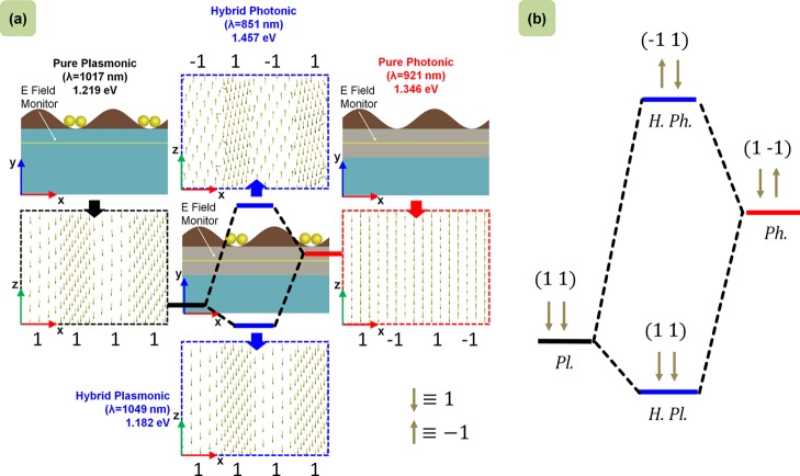
Figure 4.
Hybridization model of the plasmonic NP GMR grating by FDTD simulations. (a) Pure plasmonic and photonic modes are excited at PGR (1017 nm) and GMR (921 nm) wavelengths, respectively, in their corresponding setups. Hybridized modes are also excited at their respective resonant wavelengths (851 and 1049 nm) in the hybridized setup. The electric field vector maps (xz-plane) are plotted for all the resonant setups below the grating (fixed y-position). (b) With the vector direction definition downward (↓ ≡ +1) and upward (↑ ≡ −1), the plasmonic NP GMR hybridization model can be represented schematically.

