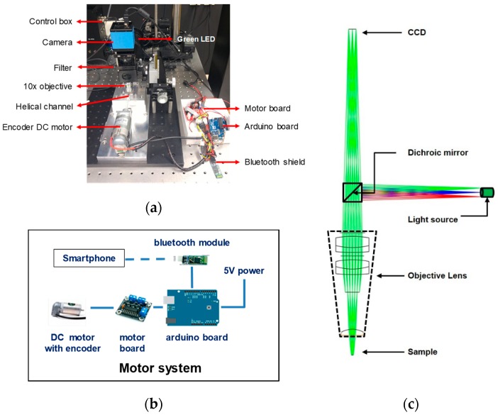
Figure 3.
(a) Experimental setup equipped with a DC motor and Arduino board to control the nut and bolt microfluidic chamber. The control box is connected to a light source. (b) Motor system comprising an Arduino board and a DC motor controlled by a smartphone wirelessly. (c) Schematic of the fluorescence imaging setup for ray tracing simulation. Wavelength of light source is in the range of 530–550 nm. Excitation and emission filters are placed in front of the excitation light source and the CCD sensor, respectively.

