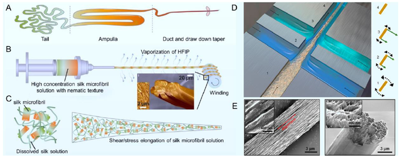
Figure 3.

A. An illustration of the silkworm spinning process in the spinning gland. B. A bioinspired spinning process that ensambles nematic silk microfibril solution into regenerated silk fibers. The inset shows a SEM image of the fiber cross section, showing the silk microfibrils are well aligned. C. Schematic of how the silk microfibrils are aligned under the shear/stress elongation. (Figures A-C adapted from Ref. 78). D. The double flow-focusing channel used for cellulose nanofibril assembly in Ref. 15. Hydrodynamic and electrostatic interactions at different positions are arranged to maximize the nanofibril alignment. E. SEM image of the fiber surface and cross sections, showing the aligned nanofibrils (Figures D-E adapted from Ref. 15).
