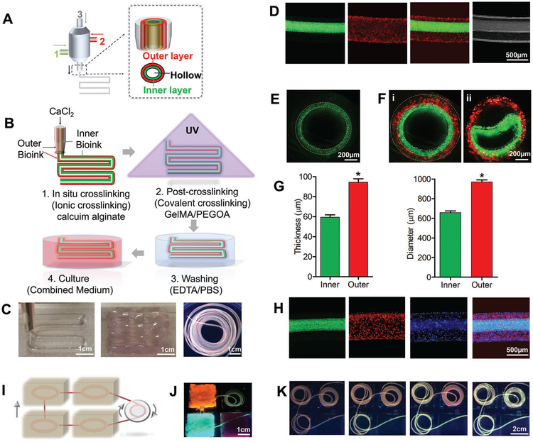
Figure 2.
3D bioprinting of circumferentially multilayered cannular tissues using the GAP bioink. A,B) Schematic illustration of the MCCES and the process of bioprinting of a multilayered hollow tube. C) Images showing bioprinted perfusable tubes with various shapes. D) Representative longitudinal fluorescence microscopy images of double-layered hollow fibers. E,F) Representative cross-sectional view fluorescent microscopy images of i) monolayered and ii) double-layered hollow fibers with fluorescent beads. G) Diameter and thickness of inner and outer layers of the bioprinted tube. H) Fluorescent microscopy images showing bioprinted tri-layered hollow tubes, where green fluorescent beads were embedded into the innermost layer, red fluorescent beads were embedded into the middle layer, and blue fluorescent beads were embedded into the outermost layer during the bioprinting process. I) Schematic of perfusion among tissues. J,K) Images showing the simulation of perfusable multiple tissues.

