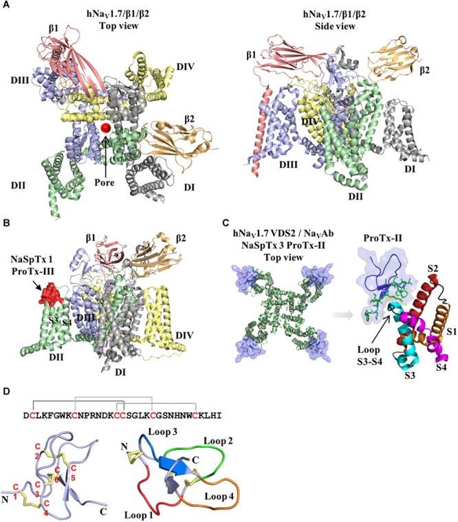
FIGURE 1.

Structure of the voltage-gated sodium channel and the inhibitory cysteine knot (ICK) spider peptide. (A) Three-dimensional structure of the human NaV1.7 in the presence of the auxiliary subunits β1 and β2 determined by cryo-EM (PDB 6J8J) (Shen et al., 2019). Top and side views are presented. The domain I (DI) is colored in gray, domain II (DII) is colored in green, domain III (DIII) is colored in blue and domain IV (DIV) is colored in yellow. The auxiliary subunits β1 and β2 are colored in salmon and orange, respectively. (B) Representative binding site of a NaSpTx 1 in the DII S3-S4 loop of the hNaV1.7 channel (PDB 6J8J) (Shen et al., 2019). Domains and auxiliary subunits are colored as in (A), and the NaSpTx1 peptide ProTx-III (PDB 2MXM) (Cardoso et al., 2015) is colored in red. (C) Detailed binding site of the NaSpTx 3 ProTx-II over the hNaV1.7 voltage–sensor domain 2 (VSD2)-NaVAb chimeric channel (PBD 6N4I) (Xu et al., 2019). Top view of the hNaV1.7 VSD2-NaVAb chimeric channel colored in green showing ProTx-II colored in blue bound to the voltage sensor domain 2 in close proximity with the S3–S4 loop. In the structure on the left, the segments S1 to S4 are colored in orange, red, cyan and magenta, respectively. The loops S1–S2 and S3–S4 are colored in black and the residues in the loop 4 and C-terminal of ProTx-II are represented by green sticks. (D) Typical structure of an inhibitory cysteine knot (ICK) peptide from spider. Primary and three-dimensional structure of ProTx-III (PDB 2MXM) (Cardoso et al., 2015) showing cysteine connectivity (C1 – C4, C2 – C5, and C3 – C6) and loops 1–4 colored in red, green, blue and orange, respectively.
