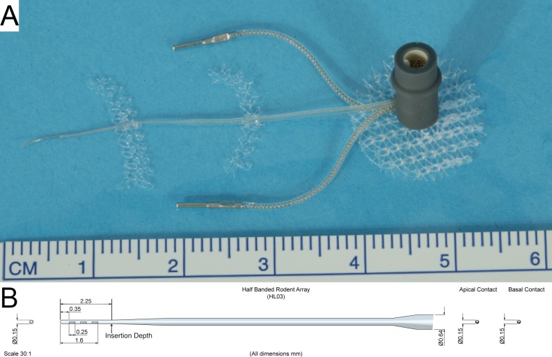
Fig 2. Electrode array assembly.
The electrode array assembly (A) and schematic (B) are pictured. The electrode assembly consisted of a 2.25 mm long and 0.15 mm wide half-banded three contact electrode intracochlear array tapering to a wider extracochlear helixed lead wire with silicone insulation along with two extracochlear electrodes connected to a transcutaneous 6-pin connector. Modified polypropylene hernia mesh is affixed strategically to enable subcutaneous fixation and stabilization of the implant.

