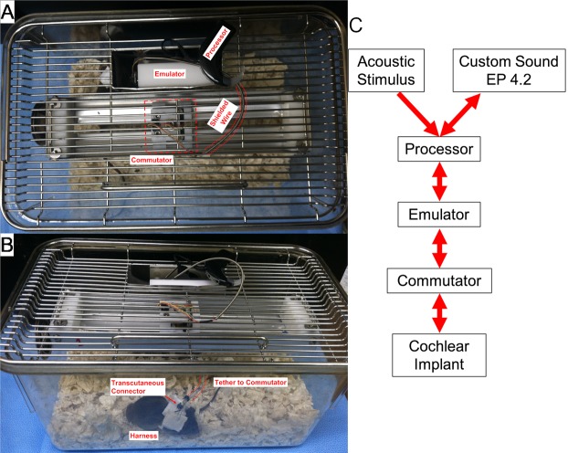
Fig 4. Example of the stimulation cage.
(A) Top down view shows the modified cage top with the implant emulator and processor within a metal enclosure. The emulator is connected to a sliding commutator via cabling protected by a spring-shield. The commutator is connected via a short length of cable which tethers to a transcutaneous connector in the electrode array assembly, which is stabilized by a harness (B). The translating commutator allows free movement of the mouse throughout the entire caging system, while maintaining electrical connectivity. (C) Diagram of the connectivity of the system with arrows denoting the direction of stimulus or recording flow.

