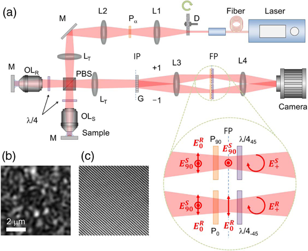
Fig. 1.

Schematic of the spatio-temporal reflection phase microscope. (a) D: diffuser; L1-L4: lenses; Pα: polarizer with α-deg rotation angle; LT: tube lens; PBS: polarizing beam splitter; λ/4α: quarter-wave plate with α-deg rotation angle; OLR and OLs: objective lenses for the reference arm and the sample arm; G: diffraction grating (the 0th diffraction order is omitted for simplicity); IP: image plane; and FP: Fourier plane; : reference beam with s-pol.; sample beam with p-pol.; : reference and sample beams with the same circular-pol. (b) Speckle distribution on the sample arm. (c) Interference fringe pattern on the camera.
