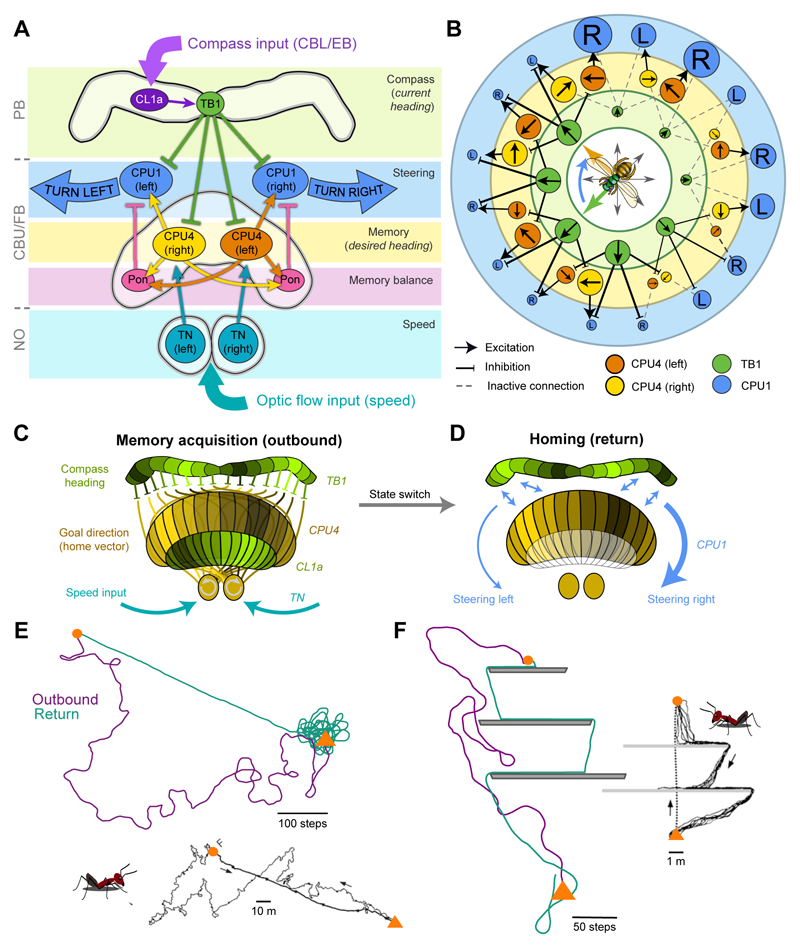
Fig. 5. The CX as neural substrate for path integration.
(A) Schematic connections between cell types in the proposed Megalopta path integrator network (Stone et al., 2017). Arrows: excitation; blunt ends: inhibition. Pon, Pontine neurons. (B) Topology of the path integration model circuit. Circles represent neurons, size of neurons indicate activity level, colour-code for model layers and cell groups as in (A). Arrows in the circles: directional tuning (TB1) and integrated direction preference (CPU4); R: right turn; L: left turn; compass rose: current (green) and desired heading (orange). (C) Illustration of the two activity bumps resulting from encoding current heading (green, in PB and EB) and target direction (yellow, in FB). The target direction results from integrating speed and compass information. (D) Steering is induced by comparing PB-activity with FB-activity column by column. The resulting imbalance in CPU1-neuron activity between the right and left side causes steering. (E) Homing behaviour produced by the path integrator model compared to desert ant data (below). Near the nest site (triangle) the model initiates searching behaviour. (F) Comparison of a desert ant (right) and the model negotiating obstacles during the homeward journey. E/F from Stone et al. (2017); inserts in E/F modified from Wehner (2003) (reproduced with permission from Elsevier).

