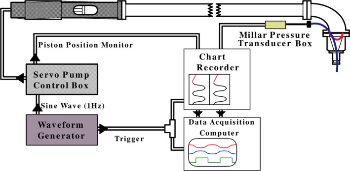
Figure 4.

Diagram of the computer‐controlled pump assembly that drove sinusoidally a volume of water into a balloon affixed to the end of the nozzle assembly and inserted into the left ventricular cavity, shown on the top right. The 8‐foot‐long horizontal column was filled with distilled water, while the balloon and nozzle were filled with deuterated water (D2O). A flexible diaphragm (indicated by the red curve inside the nozzle) separated the distilled water from the D2O.
