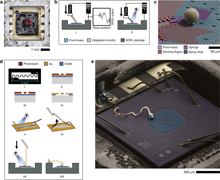
Fig. 1. Modification of post-release MEMS sensor.
a Top-view optical image of the ADXL203 die inside the package with the lid removed. The octagonal proof-mass can be seen in the center. Highlighted red box indicates the area of the proof-mass shown in the scanning electron microscope (SEM) image in (c). b Schematic of feedback-assisted attachment of microspheres onto the proof-mass. (i) ADXL output is monitored while a piezoelectric actuator lowers a micro-pipette (30 µm tip diameter) containing epoxy. Upon contact, surface forces draw out a few picoliters of epoxy and the pipette is automatically retracted. (ii) Schematic of sphere placement. ADXL output monitored as before while the sphere is lowered into the droplet. Once contact is made, the epoxy is cured by ultraviolet (UV) exposure. c Colorized SEM image of one quadrant of the micro-electromechanical system (MEMS) with a microsphere glued to the proof-mass using the micro-gluing technique. The interdigitated sensing electrodes and anchoring springs of the proof-mass can also be seen. All of the MEMS structures are 4 µm thick. d Schematic of device assembly steps. The lithography mask (i) for the nano-ribbon wire is designed with a 2 mm nominal length, 25 µm lateral width, and a 58 µm radius circle at each end for attachment. After fabricating the wires out of a 500 nm layer of evaporated Au on oxide with standard lithography and etching (ii–iv), the device is assembled (v–viii) by attaching a microsphere to one end of the wire, peeling the wire off the substrate with a pipette, then lowering the Au nano-ribbon wire (with the Ag sphere attached) onto two smaller support spheres, which have been previously bonded to the ADXL203 proof-mass using the micro-gluing technique shown in (b). e Colorized SEM image of an example of a fully modified ADXL203 (not the device used in this work)

