Figure 1.
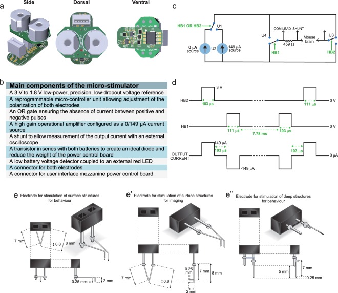
Micro-stimulator components, circuit and electrodes. (a) Simplified schematic of the micro-circuit board and battery support. (b) List of main components of the micro-stimulator. (c) Timing diagram demonstrating the offset between HB1 and HB2 as well as the summed output current. (d) Pulse duration, frequency and dead time (between positive and negative current pulses) of the stimulation paradigm. (e-e”) Types of electrodes designed for the various experimental applications: stimulation alone (e), short-term 2-photon imaging with stimulation of deep cerebral structures (e’) or long-term stimulation combined to repeated 2-photon imaging sessions (e”). Abbreviations: HB1: H bridge 1; HB2: H bridge 2; µA: microamperes; Ω: ohms, V: volts; LED: light emitting diode.

