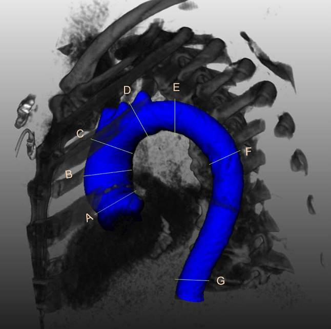
Fig. 1.

3D reconstruction of the thoracic aorta showing the level of the 7 locations where measurements were performed. A = sinotubular junction (at the connection of the aortic root and the ascending aorta); B = mid ascending aorta (at the level of the pulmonary trunk); C = proximal aortic arch (at the origin of the brachiocephalic trunk); D = mid aortic arch (between the left carotid artery and the left subclavian artery; after the left vertebral artery if it had a separate origin from the aorta); E = proximal descending thoracic aorta (at approximately 2 cm distal to the left subclavian artery; however if at this level there was either a dilatation or a steep bending of the aorta, the plane was moved closer to the left subclavian artery); F = mid descending aorta (at the same level as the MAA); G = diaphragm
