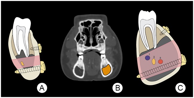
Fig 12. Illustration of theoretical space available for mono- and bicortical screw insertion.
Here (A) is an illustration of the human mandibular body (after the AO Foundation, Switzerland), showing the potential space for positioning both mono- and bicortical screws. The pink area indicates a zone, which extends from the tooth roots to the inferior aspect of the mandibular canal that conveys the inferior alveolar nerve and its associated blood vessels. The yellow oval indicates the inferior alveolar nerve. Image (B) is a transverse plane CT image of a 21 months-old minipig head at the level of the first premolar tooth. The area coloured in orange indicates the dimensions of the mandibular canal. Illustration (C) depicts the right mandibular body of the minipig seen in (B), showing one extreme of the highly variable mandibular canal dimensions and the potential space for positioning both mono- and bicortical screws. The pink area indicates a zone where the inferior alveolar nerves and blood vessels are located. Portrayed is the inferior alveolar neurovascular bundle consisting of the inferior alveolar vein (1), the inferior alveolar nerve (2) and the inferior alveolar artery (3).

