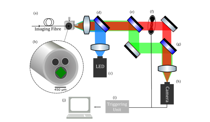
Fig. 1.
Ratiometric imaging system. Panoptes imaging fibre (a) consisting of a tessellated array of 8100 cores (b). A blue LED (c) is coupled via a dichroic mirror (d) into the fibre bundle. The fluorescence emission is separated by a second dichroic mirror (e) about 605 nm. The long wavelength path is interrupted by an optical chopper (f) and recombined with another dichroic mirror (g) onto a monochromatic camera (h). A PC (j) is used to control a triggering unit (i) with outputs to the camera and the chopper.

